
Metro Access Networks
Cross-connect cabinets and splitter boxes that keep subscriber drops separated and easy to re-route.
- Optical cable cross-connect cabinet
- Optical splitter box
- Patching and re-routing flexibility
Site type, route, subscriber density, split ratio, node capacity, sealing and termination method change what a suitable ODN layout looks like.
Use each profile as a starting point, then validate the actual topology, cable counts, node capacity and split ratio.
Cross-connect cabinets and splitter boxes that keep subscriber drops separated and easy to re-route.
Fiber distribution boxes at building level, with drop cable branching to each unit.
Floor boxes and terminal boxes that keep riser cable counts and labels under control.
Optical fiber distribution frames with organised patching, testing and cable records.
Joint closures rated for water, dust and mechanical load along buried cable spans.
Split ratios and cable types chosen to protect the loss budget over long feeder runs.
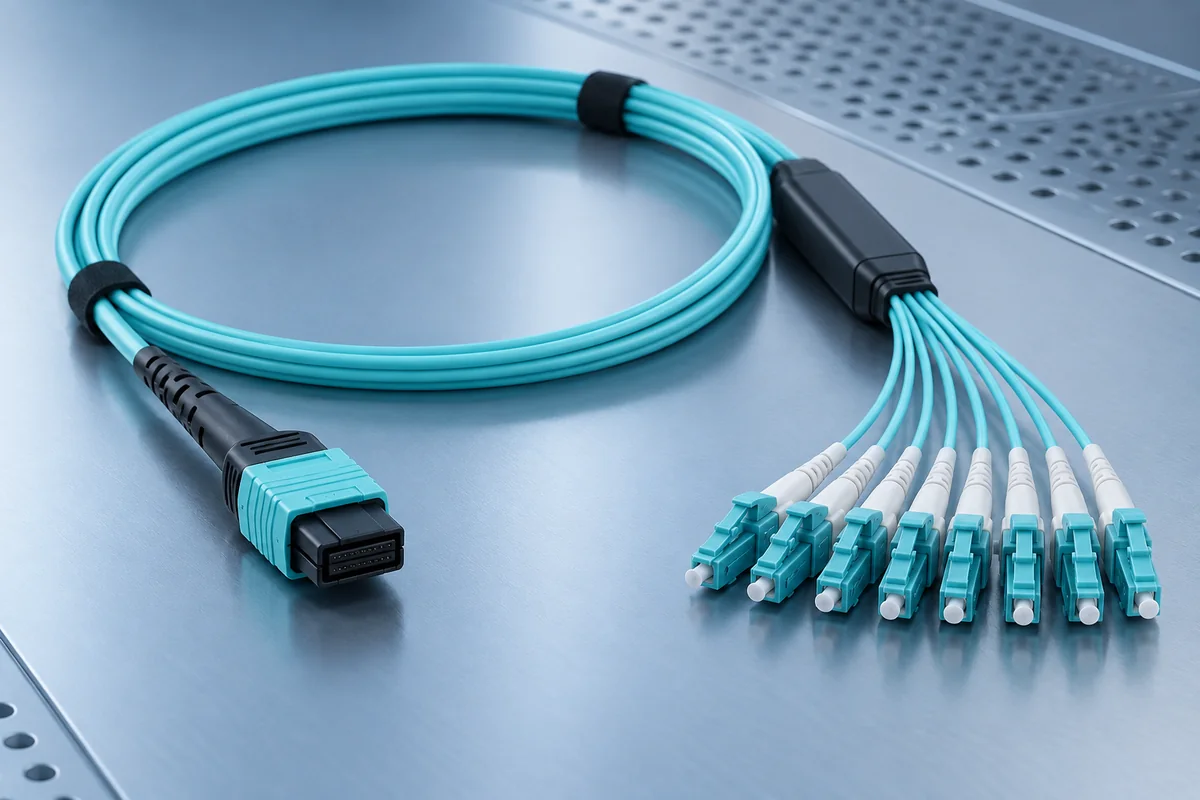
More ports can save future work, but node capacity, splitter module size, cable entry and re-entry access become more important. Rural routes may need fewer nodes yet demand better sealing and a larger loss budget margin.
A useful ODN specification answers these questions even when the deployment environment changes.
Record feeder, distribution and drop segments, split points and the split ratio the loss budget allows.
Count first-year subscribers and add margin for later fill when sizing boxes and cabinets.
Confirm duct, manhole, aerial, wall or rack mounting and the required IP or mechanical rating.
Define inspection, continuity, insertion loss and OTDR requirements before commissioning the ODN.
Network scale, split ratio, node capacity and sealing requirements are the most useful first details.