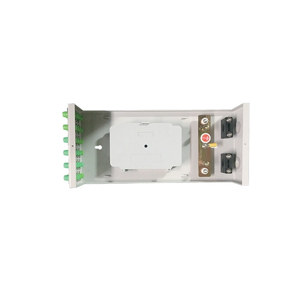
A secondary distribution box receives low-voltage power from a transformer and distributes it to multiple circuits through protective devices like MCBs, RCDs, and busbars.Overview of Secondary Distribution Systems
Secondary distribution systems operate at low voltage (typically 100–240 V AC) and deliver power from distribution transformers to end-user circuits. The configuration depends on the number of phases, required reliability, and load density. Common topologies include:
- Radial System: Each circuit is supplied from a single transformer; simple but less reliable if a fault occurs .
- Selective Radial: Two primary incoming circuits with a tie breaker; limits outage duration by switching to the second circuit .
- Loop Selective: Substations are fed from two sources in a loop, improving reliability and allowing service restoration without interrupting all loads .
Components of a Secondary Distribution Box
A typical secondary distribution box includes :
- Main Switch/Isolator: Controls incoming power and allows isolation for maintenance.
- Surge Protective Device (SPD): Protects circuits from voltage spikes.
- Miniature Circuit Breakers (MCBs): Protect individual outgoing circuits from overloads and short circuits.
- Residual Current Devices (RCDs) or RCBOs: Provide earth fault protection.
- Busbars: Conductors for distributing phase and neutral connections.
- Neutral Bar and Earth Bar: Central points for neutral and protective earth connections.
- Outgoing Circuits: Branch circuits supplying power to loads.
Simplified System Diagram
Incoming Supply L N PE | +--------------------+ | | Main Switch/Isolator Earth Bar PE | +--------------------+ | | Phase Busbar Neutral Bar | | +---+---+---+ +---+---+---+ | MCB | MCB | MCB | | N1 N2 N3| +---+---+---+ +---+---+---+ | | Outgoing Circuits L1 L2 L3 | SPD Module
This diagram illustrates the flow of power from the incoming supply through protective devices to the outgoing circuits. The SPD module is connected between line and neutral or line and earth to mitigate transient surges.
Design Considerations
- Proximity to Load: Secondary distribution boxes are often located close to the load to minimize cable lengths and voltage drops .
- Load Balancing: Circuits should be distributed evenly across phases to prevent overloading.
- Future Expansion: Include spare ways for additional circuits.
- Compliance: Follow local codes and standards such as IEC 61439, IEC 60898, or UL/NEC.
- Environmental Protection: Consider IP rating, UV resistance, and corrosion protection for outdoor installations.
Summary
A secondary distribution box is a critical component in low-voltage distribution, ensuring safe and reliable delivery of electricity to multiple circuits. Its configuration can vary from simple radial to looped selective systems, with internal components designed to protect, isolate, and distribute power efficiently. Proper design ensures minimal voltage drop, high reliability, and compliance with safety standards .